
Experiments
PURPOSE of doing this experiment is that it helps the students in understanding
- What is a counter?
- Why is it used?
- Working of counter
What Is Counter?
Counter is an important element in digital electronics, which we use the most. Counters are used not only for counting purposes but also they are found useful in measuring frequency and time; increasing or decreasing numbers like memory addresses.
Counters are designed with the help of synchronous sequential circuits which always use the clock signal, in which, the counter counts the number of clock pulses used to trigger the flip-flops, a basic memory element of synchronous sequential circuits..
Why Are Counters Used?
As we know the count means increasing or decreasing the values, with respect to its previous value. So to perform increasing or decreasing operation we use counters. This function is not possible to be performed with any other logic devices except counters.
Working of Counters
To understand the working of counters, let us first understand the types of counters. There are two types of counters available for digital circuits, they are
- Synchronous counters
- Asynchronous counters
Different types of counters are explained below.
Synchronous counters
Synchrounous counters are those counters which use a same clock signal to change their count.or we can say that the synchronous counters depend on their common clock input to change state values of their flip flops connected to form synchronous counters and all flip-flops used to work as the synchronous counters are triggered by the same clock signal.
Features:
- They are very simple to construct.
- As all the flip-flops are triggered by the same clock signal, all are synchronized and hence don’t require settling.
- Their speed of operation is fast.
- But the drawback of these is that we require a number of logic gates to be connected to implement the synchronous counters.
Asynchronous counters
The counters in which the clock pulses are counted in an asynchronous manner are known as “Asynchronous counters”.They also belong to the category of synchronous sequential circuits because of the use of clock signal. In these counters, the first flip-flop is triggered(I. e. it states is changed according to the input at the specified time provided by the clock signal) by the external clock signal, and the remaining flip-flops are clocked or triggered by the state outputs (Q & Q’) of their previous flip-flops. So they are also named as Ripple Counters.
Features of Asynchronous Counters:
- Simple Construction
- As it is simple, they require less number of logic gates to make up an asynchronous counter.
- But drawback is that Speed operation of asynchronous counters is very slow as compared to synchronous counters.
INFRASTRUCTURE
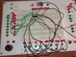
In the laboratory, the function of counters is verified using in the 4-bit synchronous counter kit, IC 7476 whose IC diagram is as follows
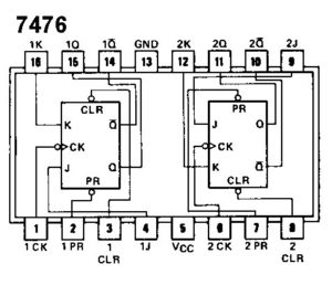
Also, the function generator is used to generate clock pulses and thus function of counters is verified by counting the number of these clock pulses.
USP
The USP of this experiment is the visual reflection of working on the counter with the ON and OFF of LEDs according to the count it has to display.
PURPOSE of doing this experiment is that it makes students aware of the use of digital logic circuits in arithmetic (addition) functions.
Students are imparted knowledge of
- What is parallel adder?
- How is it implemented?
- Applications of Parallel Adder
What Is Parallel Adder?
Adders are the combinational circuits which are used to add two binary numbers. The type of the adders to be selected depends on the features of the binary numbers which are to be added. Let us take an example, if we want to add two binary numbers of single bit each, then it can be done by using a combinational circuit known as half adder while if there is an input carry present along with the two binary numbers which is to be added along with them, then one must make use of combinational circuit known as full adder. However what if we want to add two binary number having more than one bit i.e. n-bit each. In such a case, the need arises to use a parallel adder. . Parallel adder is a combinational circuit which is used for adding correspondingly every bit position of the two binary numberssimultaneouslyThus it needs that much number of full adders as the number of bits present in the binary numbers to be added.
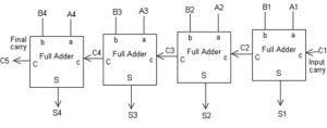
The schematic diagram of a 4-bit parallel adder is shown below.
As shown in above two binary numbers if 4-bit each are added in a way that each corresponding bit of two numbers is added individually along with their carry inputs using full adder in a parallel form and corresponding sum value is noted down, carry output of each full adder is given as carry input of next stage till we get last carry that is a final carry output.
INFRASTRUCTURE
How Is Parallel Adder Implemented?
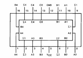
In the digital electronics laboratory, 7483IC is used to implement the function of parallel adder whose pin diagram is as follows:-
It is a 4-bit parallel adder IC which accomplishes the binary addition of two 4-bit numbers along with input carry and give output in the form of the sum and carry (if any).
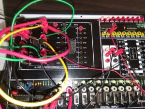
We make use of an In-House Kit (Analog to Digital Trainer Kit- Made by Students in collaboration with faculty) which has breadboard on which suitable components and their connections are made.
Applications Of Parallel Adder
It can be used in op-amp circuits, that is as comparators or differentiators. The application of a 4-bit adder is for use as part of the core of an ALU, or arithmetic logic unit.
USP
The USP of this laboratory is the In-House Kit (Analog to Digital Trainer kit). This equipment which is not purchased from anywhere, rather it is made by the students of Electronics & Communication Engineering department in consultation with the faculty of the department.


