Experiments
Purpose of the Practical (Serial Communication): In Rs232 protocol transmission one bit is sent over a time interval, over a single communications line. Moreover in parallel communications require at least as many lines as there are bits in a word being transmitted (for an 8-bit word, a minimum of 8 lines are needed). RS232 Serial transmission is used for long-distance communications, whereas parallel communication is for short distances or when very high transmission rates are required.
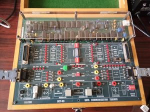
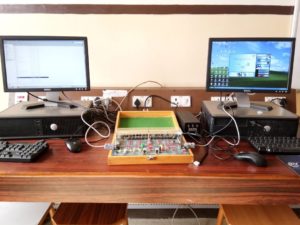
Infrastructure: DCT-03 Kit, 9 Pin D connector cables, Computers, connecting Chords and Power supply.
RS232-Standards
The advantage of the RS-232 protocol includes transmission over telephone lines. The serial digital data can be converted by modem, placed over a telephone line, and converted back to serial data by the second modem.
In RS-232 data terminal equipment (DTE) is the computer, while data communications equipment (DCE) is the modem. The connection is established between DTE and DCE.
The RS-232 protocol is significantly used for connections between data acquisition devices and computer systems. When DCE is not available, Null modems are used.
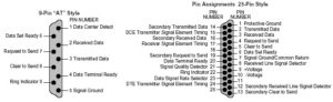
RS-232 cables are commonly available in 4, 9 or 25-pin wiring. . The 25-pin Rs232 cable connects every pin; the 9-pin Rs232 cables do not include many of the uncommonly used connections; 4-pin Rs232 cables provide the bare minimum connections, and have jumpers to provide “handshaking” for those devices that require it.
RS-232 PINOUT
TRANSMITTED SIGNAL
VOLTAGE LEVELS:
Binary 0: +5 to +15 Vdc (called a ” space” or “on”)
Binary 1: -5 to -15 Vdc (called a “mark” or “off”)
RECEIVED SIGNAL
VOLTAGE LEVELS:
Binary 0: +3 to +13 Vdc
Binary 1: -3 to -13 Vdc
DATA FORMAT
Start bit: Binary 0
Data: 5, 6, 7 or 8 bits
Parity: Odd, even, mark or space (not used with 8-bit data)
Stop bit: Binary 1, one or two bits
 Data and control signals
The following table lists commonly used RS-232 signals :
| Circuit | Direction | DB-25 pin | |||
| Name | Typical purpose | Abbreviation | DTE | DCE | |
| Data Terminal Ready | DTE is ready to receive, initiate, or continue a call. | DTR | out | in | 20 |
| Data Carrier Detect | DCE is receiving a carrier from a remote DCE. | DCD | in | out | 8 |
| Data Set Ready | DCE is ready to receive and send data. | DSR | in | out | 6 |
| Ring Indicator | DCE has detected an incoming ring signal on the telephone line. | RI | in | out | 22 |
| Request To Send | DTE requests the DCE prepare to transmit data. | RTS | out | in | 4 |
| Ready To Receive | DTE is ready to receive data from DCE. If in use, RTS is assumed to be always asserted. | RTR | out | in | 4 |
| Clear To Send | DCE is ready to accept data from the DTE. | CTS | in | out | 5 |
| Transmitted Data | Carries data from DTE to DCE. | TxD | out | in | 2 |
| Received Data | Carries data from DCE to DTE. | RxD | in | out | 3 |
| Common Ground | Zero voltage reference for all of the above. | GND | common | 7 | |
| Protective Ground | Connected to chassis ground. | PG | common | 1 | |
USP: Students get to know the advantage of RS-232 protocol, that includes transmission over telephone lines.